OverviewStorage Retrieval System A valued Smock customer required a storage retrieval system to feed their machine that could store various sizes and quantities of sheet metal blanks in order to free up valuable floor space, provide inventory control and reduce handling cost. In working closely with the customer, our sales engineers and designers developed the concept that would fit the customer needs and a quote to the customer followed. The resulting system required a load/unload station, a pick and place system, a storage rack and pallets, a machine load station, safety fencing and controls to tie it all together. Our in-house design engineers designed and detailed the required components while working with the customer to insure they got a solution that would meet their needs. After the design was completed and final approval was granted, the fabrication and vendor sourcing proceeded. We worked closely with our vendors to meet the timeline and quoted price to the customer. Our experienced staff of shop personnel began to fabricating some of the components in our 15,000 sq. ft. shop area. As vendor supplied items began coming in, our shop personnel began to assemble the system. At various stages of completion, we tested the system to insure it met all the requirement of the customer order and any additional changes that would create value and safety for the customer. The customer provided us with the machine our system was to feed and we integrated it with the system we were supplying at our facility on our shop floor. After additional tests, the customer was invited for runoff. We worked with the customer and their manufacturing personnel to insure they not only got what they ordered but what they needed. During the runoff, the customer manufactured a small batch of parts as a test and to provide prototypes for their new product line. Additionally, we provided hands-on training to the customers manufacturing personnel on the operation of the system. After the final runoff and few minor controls changes, we carefully packed the system to insure that it arrived at the customers facility in good condition. With our engineering manager overseeing onsite installation, our in-house personnel installed the completed system with attention to detail and safety. After installation and a period of on operation, the customer determined that additional control system changes were needed due to changes in their product requirements. Our controls staff took the customers needs and translated them into PLC program changes that helped the customer become even more efficient. At Smock we make every effort to create an ongoing partnership with our customers.
|
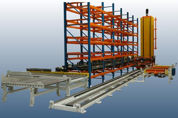 entire storage retrieval system Goals: To design, build, test and install a robust system for handling, positioning and storing pallets of blank sheet stock for a roll-forming process. The system included a way to identify new pallets of blanks introduced via fork truck and track them through the process by way of a bar code reader. The pallets are placed in a storage rack and the system maintains pallet part number, storage location and sheet quantity information. The system retrieves pallets from the storage rack and positions them so that the roll-former can remove one blank sheet at a time. The system retrieved the pallets based on the blank part number and the number of blanks required for each batch run. Empty pallets are sent to the unload station conveyor for fork truck removal. Partial pallets are returned to the storage rack with updated part quantity information.
|
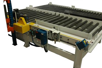
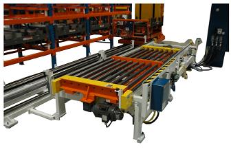
view of load and unload station The load station conveyor consists of two zones. Each zone contains ten (10) electrically powered chain driven rollers. A pneumatic clutch/brake controls the actuation of each zone of rollers. Steel set-down guides are bolted to the load station conveyor frame to assist the fork truck operator when loading a pallet. An emergency stop pushbutton is also located at the end of the load station conveyor. The unload station conveyor contains (30) gravity hex spring retained rollers and a bolt on steel end plate. Photo-eyes are installed on each zone of the conveyors to detect pallets.
|
|
|
|
|
|
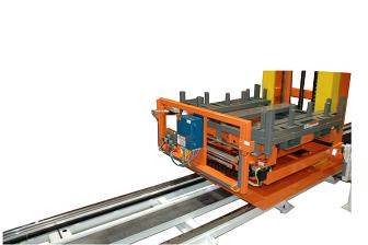
view of machine load station The machine load station assembly consists of a fabricated steel base frame containing two (2) fabricated steel pop-up conveyors. The pop-up conveyors each contain eight (8) electrically powered chain driven rollers and four (4) pneumatic air bags with quick exhausts that control the raising and lowering of the conveyors. A gravity roller is located at the entry to the conveyors to assist the pallets as they transfer to and from the stacker. The cross transfer reversing conveyor contains chains that are powered by an electric variable frequency drive and guided on rails.
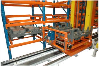
view of storage rack The storage rack consists of steel uprights and steel beams bolted together to form the rack. Each rack bay contains a fabricated steel fixture that the pallet rests on. A photo-eye reflector is mounted to one leg of each steel fixture to ensure the stacker is in position to allow the carriage to extend into the storage bay.
|
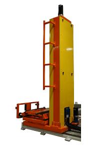
view of stacker The stacker consists of a fabricated steel frame with a bolted on fabricated steel carriage assembly. The stacker carriage assembly contains a telescoping chain transfer device powered by an electric brake motor. The chain transfer is mounted onto rails and utilizes a pneumatic cylinder with flow controls to control motion. The stacker motion and carriage motion is controlled by separate electric servo motors with brakes. The stacker carriage utilizes a ball screw assembly to move it up and down on steel rails. Urethane bumpers are installed on the base frame of the stacker assembly to protect the carriage in the event of an over-travel sensor failure. A barcode scanner is mounted to the stacker carriage.
view of stacker rails The stacker travels on steel rails bolted to steel track sections. The track sections are bolted together to form one continuous track. The track is anchored level to the floor in multiple places. The stacker utilizes a pinion gear to guide it along the track. Rubber bumpers are installed at the ends of the track to protect the stacker carriage in the event of an over-travel sensor failure. A steel wire way duct with steel cap sections is built into the center of the track. The wire way houses all the power cables and pneumatic hoses for the stacker device.
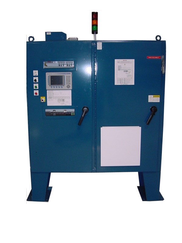
view of main control panel The control logic and components for the Storage Retrieval System are provided through the main control panel. The HMI operator interface is mounted on the front of the Main Control Panel. A key switch is located on the side of the panel. The key switch provides a system override selection. The key switch can be placed in three (3) separate positions; Roll Mach, Both, and Pallet Conv.
|